Rainbow in a Colorless Gem
Author's Preface
This article on the quantitative analysis of 'fire' in a faceted gem was first completed in year 1991. Thanks to a personal contribution by Yulia Petrovna Solodova, it was published in 1995 in Proceedings of Wroclaw University, Poland [1].
We now present a revised and amended version of the article, which has been modified as follows:
-
- Corrections of grammar mistakes and wrong symbols, those introduced in the Polish edition due to bad Russian.
- More detailed explanations of certain issues were provided (derivations of certain formulae, Figures 4 and 7).
- The paragraph on un-flat facets was added, a matter, which has been repeatedly raised in discussions of the article [1].
- The paragraph commenting on the error found in "Modeling the Appearance of The Round Brilliant Cut Diamond: An Analysis of Fire, and More About Brilliance, Gems & Gemology, Fall 2001". The dependence of the color beam dispersion on the angle of departure of the beam from the gem has been already discussed in gemology literature. Cf. e.g. the series of articles by M.Elbe published in "Zeitscrift der Deutschen gemmologischen Gesellschaft" magazine, Germany, in the early 1970's.
- The English variant of article was edited and improved by Bruce L.
Harding.
The author's logic, the course of disclosure, the conclusions, the results, the table and all figures of the paper were left intact.
Rainbow in a Colorless Gem
The day that Man took his first interest in gems has faded into the dimness of the past. Archaeological excavations have shown that gems played an important role in human cultural affairs as early as in the 4th millennium B C.
However, gem-cutting with flat facets appeared much later, about 1400 A D. Flat facets were a revolution in the field of gems, assigning the highest value to transparent gems and played the decisive role in the destiny of diamonds by turning them from a plain hard rarity into the King of Gems.
Natural diamond crystals have a basically octahedral shape,which prevents dispersion of white light into rainbow colors - the feature inherent in a faceted gem. Spontaneous development, by trial-and-error of cutting shape evolved - as late as in the XVIII century brilliant style. This shape has survived to current times and became the classical cut of diamond having even number of facets at the pavilion and on the bezel (see Fig. 1).
 Fig. 1. The classical cut of diamond.
This form is related to the shape of natural octahedron of diamond crystals. The "Diamond Design" by M. Tolkowsky, first published in 1919 [1, 11], has been the most well-known, although not the first, serious attempt to mathematically justify the proportions empirically found by that time.
Despite some errors in the initial assumptions [2, 11], the proportions and slope angles of the base facets as calculated by Tolkowsky were quite successful and have been adopted as ideal in many countries. Nowadays, calculations prove to be useful for other materials in connection with expansion of the range of minerals employed in jewelry and emerging of new synthetic crystals often surpassing natural ones in optical properties.
The attraction of colorless and low-colored gems is in the colored light coming from the gem's facets changing color with gem rotation. The ability of an even colorless cut gem to produce colored rays from the stone is called "fire". The Russian term which best describes this phenomenon is "igra kamnya" - i.e. "the play of the gem". This is what we will discuss in this article. Now let's see where the color comes from and how to maximize its intensity.
White color is known to be a combination of many colors. Traditional sources of light, such as the Sun, an incandescent lamp and other high-temperature bodies emit a spectrum of light, of which a human eye can perceive only wavelengths within the range of 380 to 760 nm (from violet to red colors). The combination of all these wavelengths is seen as white or nearly white color.
Perception of a color other then white can occur if certain wavelengths from the visible part of the spectrum are isolated. The most saturated color is seen when the retina is entered by radiation with the narrowest range of wavelengths. The width of this range is determined primarily by gem's cut. First we have to determine how narrow it should be for the observer to see a "pure color".
Using the standard colorimetric observer addition functions established in 1931 by the 8th Session of CIE (Commission International de l'Eclairage), any spectral composition of radiation can be reduced to a certain color [3], including calculation of the color and its saturation to the observer's eye in a fixed wavelength range. Fig.2 shows the relationship between the saturation of the light P being seen and its dominant wavelength l, at various selected wavelength intervals Dl.
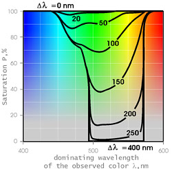
Fig. 2. The saturation of observed color and its dominant wavelength l in dependence at various selected wavelength intervals Dl.
The calculations were based on direct sun light spectrum (Source B, GOST 7721-76 -Russian standard), but it should be emphasized that the resulting estimates are not significantly affected by which reference is used. As the figure shows, the increasing the Dl interval degrades saturation of green rays first. This is the range of the human eye has greatest sensitivity to variations of color saturation. For example, for green, DIN 6164 (Germany) color standard defines 17 color saturation grades, and Mansell Color System (USA), defines 15, with the difference between adjoining grades within 10 to 20%. For low saturated color grades the difference is about 5%.
Hence, we assume that a human eye will perceive the colors with saturation exceeding 80% as really pure colors, and those with saturation under 5% as colorless. One can see, from Fig. 2, that for Dl < 50 nm all rays prove to be well-colored, while all tints of green disappear totally at Dl > 200 nm.
It should be emphasized that blue and red colors possess high levels of saturation even at very high values of Dl, but this fact should not mislead anybody. The thing is, that saturated blue and red color would appear if either end of the Dl range extends beyond the limits of the visible part of the spectrum. In this study, the color perceived by the eye shall be determined solely by the width of the Dl located within the visible part of the spectrum. The intensity of these blue and red rays is far below that of the low-colored beams of other rays and the probability of their detection becomes negligible.
In order to isolate an interval of wavelengths Dl, radiations of different wavelengths must be separated. For this purpose, one can employ either the phenomenon of optical interference, which provides for fire in nacre, noble opal, or iridescent feldspar, or the phenomenon of dispersion providing for fire in faceted gems.
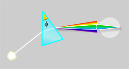
Fig. 3. Refraction of white light beam.
A beam of light passing through a wedge of any substance (see Fig. 3) experiences the change in the direction of light propagation, which is called refraction. The higher is the refractive index 'n'of the substance, the higher is the angle of refraction. Due to radiation interaction with the substance (which consist of set of oscillators), the index 'n' value in transparent media depends on the wavelength, increasing for shorter wavelengths. This phenomenon is called dispersion, or Dn, which is expressed as the difference of 'n' values between violet (Fraunhofer-line G 431 nm) and red (line B 687 nm) ends of spectrum. The following Table lists Dn values for a variety of materials.
|
The Table shows the values of dispersion to vary strongly for various faceting materials. It is the dispersion value that determines the width of the color fan the white ray is dispersed into. Note that the relationship between the wavelength and the refractive index is not linear (see Fig. 4).
Fig. 4. Yttrium-aluminum garnet refraction index values for various wavelengths.
In the blue - violet range, the index of refraction value grows, with decreasing wavelength, much faster than in other spectrum ranges. This relationship in the visible part of the spectrum is sometimes described with the hyperbola set as follows: ,
where. Such behavior of n(l) curve is determined by proximity of the edge of ultraviolet characteristic electronic absorption. We shall neglect this peculiarity for the sake of simplicity in further estimations.
Capacity of a prism to decompose a white ray is called angular dispersion of the prism, expressed in degree/mm; that is the change of ray angle per micron of wavelength change.
Let us consider the observer's eye (see Fig.3) focused at the facet of the prism nearest to it, that is, looking at the prism. The sharp image of the facet is thereat formed on the eye's retina, each point on the facet surface being mapped with a retina point. The Figure shows passage of rays through one such point on the prism's facet. The beam leaving the prism forms a fan-shaped bundle of rays of various colors.
Actually, the ray begins to disperse upon entering the prism, but this is much less than at exit. Because the prism size is negligible compared to its distance from the eye, we will neglect the input dispersion. Should all this 'fan' enter the pupil of the eye, the eye's lens will focus all of it into a white-colored dot on the retina.
However, if the fan area exceeds pupil size at the eye location, then only a part of the 'fan' cut-off with the pupil would be focused on the retina.
The distance from the gem to the observer can vary, so instead of linear pupil size it is more convenient to employ its angular size, i.e. the angle at which the pupil diameter is seen from the gem. If the angular 'fan' size exceeds the angular pupil diameter, then only a part of complete visible spectrum radiation of certain wavelengths will hit the focused dot on the retina.
The higher the prism angular dispersion and the narrower the pupil, the narrower would be the wavelength band Dl cut off from the complete spectrum, resulting in higher saturation of the colors observed.
As gems are usually viewed in good illumination conditions and from convenient distances, the pupil diameter can be assumed 3 mm and the distance to the gem being that of normal viewing, that is, 25 cm. Then the pupil angular size will be 0.7 degrees. To isolate for this size the wavelength interval Dl = 50 nm providing for obtaining "pure colors" will require the gem angular dispersion of at least 14 degree/mm. Angular dispersion values inferior to 3.5 degree/mm leads to complete loss of green color, the other colors being observed rather rarely. It should be emphasized that the fire improves with increasing distances between the gem and the observer and diminishes at lower illumination conditions, which make the pupil expand.
The above is true only if the prism is illuminated with a plane light wave. Such illumination is generated by a point source, that is, the one located at the distance much greter than its own size; in other words, it is a source of a small angular size. For an expanded source of illumination, the rays emitted from its different points and entering the prism from different directions would mix their colors on the retina, degrading the purity of the observed color. Hence, good fire requires illumination of the gem from a light source of small angular size. The source angular size affects the color purity similarly to the observer's eye pupil size.
Since the angular size of the sun, a lamp or a candle does not exceed 0.5 degree, the fire depends primarily on the pupil angular size. The fire of colorless gems is perfect in the sunlight and even better in illumination coming from multiple point sources, such as a chandelier with many lamps without matted shades or a candelabrum with candles. Then the number of color "fans" from a gem will increase by, as many times as there will be the sources of light. The fire from a faceted gem will be completely lost in the light of a dull day under cloudy sky.
All this should be always kept in mind by those engaged in sales or advertising of precious stones or those choosing jewelry for tonight's party.
Up to now, we have considered a prism with have ideally planar facets. It has the following two shortcomings which we could try to rectify using curved surfaces:
-
- If the visible angular facet size exceeds the angular size of the light source, then only the area conducting the light image from the source of the facet will be shining.
- The source image visible through the prism is a part of a rainbow. For better color perception, uniform facet coloring is desirable.
Placing convex lenses immediately before and after the prism, so that the light source and the observer's eye pupil located in their outer focal planes would make all facet surfaces uniformly colored. However, such a system would only be tuned to fixed distances. Replacement of lenses with curvature of prism surfaces (gem facets) would cause to strong astigmatism. Besides, the required curvature radii shall thereat be very long, similar to the distance between the observer and the gem. Cutting gems actually produces curvature of the facet surfaces due to limited rigidity of cutting head, spindle, polish and many other factors. This uncontrolled curvature usually exceeds the desired one. Hence, to improve fire, the cutter should try to produce facets as flat as possible.
Fig. 5. Ray refraction.
Optically, a cut gem is a set of wedges out of the gem substance. Fig. 5 shows one such refraction wedge.
The wedge 'angular dispersion' depends on the angle of the beam incidence and the angle of the beam departure corresponding to it. It can be calculated from the following equation, derivation of which is given, for example, in [5]:
where: F is prism vertex angle, y is the angle of the beam incidence to the prism, j is the angle of the beam departure.
Because of the non-linearity of n(l) (see Fig.4) we calculate using dn/dl slope of that curve at 515 nm (see Table) because that is the region of maximum sensitivity of our eyes to impurity of color. Hence, we see the value of the aperture of the fan is proportional to the value of the substance dispersion and the vertex angle sine, that is, it increases with increasing of this angle. Note that angle y is inside the prism, while j is outside it. This expression is inconvenient; the angular dispersion dj/dl is best calculated by steps.
As an example, Fig 6 presents angular dispersion of the optical wedge of fianite (the Russian name for cubic zirconia's dioxide) versus angle of beam departure j, calculated for four different vertex angledes F.
Fig. 6. Angular dispersion of optical wedges of fianite with various vertex angles versus angle of beam departure.
With angle j increasing up to 90 degrees, the angular dispersion grows sharply; its minimum is near j = 0. The latter is very important - this is the viewing angle of the table when viewing the gem normal to the table or with a small inclination. If we manage to provide the 14 deg/mm angular dispersion for this case, then all rays departing from the gem would have pure colors.
The sharp rise of dispersion at high angles of departure explains the fire phenomenon to occur, although not so often, at certain angles even for poorly cut gems and gems having low dispersion. Special cut shapes have been suggested, such as the "impariant" [6] calculated specially for high angles of beam departure to air; however, the fire of such rays can only be viewed on a slant, next to along its surface, so we shall not consider these cases here.
Line A, corresponding to minimum j values, limits the range of possible beam departure angles. With the prism vertex angle exceeding the limit angle of total internal reflection![]() , no incident beam could leave the prism normal to its facet. Meanwhile, the observer was placed just perpendicular to the table, hence, angle F = g is the maximum admissible for the wedge vertex. Let us note that no beam of light would pass through the wedge at F > 2g.
, no incident beam could leave the prism normal to its facet. Meanwhile, the observer was placed just perpendicular to the table, hence, angle F = g is the maximum admissible for the wedge vertex. Let us note that no beam of light would pass through the wedge at F > 2g.
The last column of the Table gives minimum values of angular dispersion for a prism having vertex angle g. It is by this parameter that crystals described in the Table have been sorted. As the Table shows, only first three synthetic materials of the listed are able to provide perfect fire. In fact, well-faceted rutile, in the aspect of fire, is similar to noble opal. There exist natural minerals, such as sphalerite, having as good optical properties, but low mechanical characteristics. The materials in lines four through nine display fire of varied degree of saturation. In case of doubt, consider diamond: green colors can hardly be seen in its fire.
Apparently the attraction of a cut diamond is mainly due to its perfectly polished facets and flatness of the facets resulting from high rigidity of the cast iron polishing wheel. The last four minerals from the table are able to color only a few departing beams of light, which is - regretfully - characteristic of the majority of natural minerals. Hence a gem cutter must do his utmost to enhance the fire on natural minerals.
Note that beams departing (see Fig. 6, right-hand side) from the prism at high angles to the prism plane are dispersed many times more efficiently than incident beams entering the prism at high angles (see Fig. 6 left-hand side). In other words, the angular dispersion value is larger for ABCD path (see Fig.5) than for DCBA one. Ignorance of this fact may sometimes lead to very sad mistakes, for example, it devaluates the results of study of the gem fire [7]. Specifically, the fire in this study is assessed through rays departing from the gem in all directions within the top hemisphere. That means that the observer is distributed across the space, being located in a separate site for each ray, while the source illuminates the gem normally to the table. The authors of work [7] believe that they consider the gem normally to the table. Actually, these two cases differ greatly. Moreover, one can state that beams possessing maximum fire at illumination perpendicular to the table, would correspond to low-colored flashes on its surface being viewed normally to the table!
Now let's consider the wedge of the substance the light ray passes through in the real gem and what can be done to expand the vertex angle. For this purpose, one can track the path of various rays through the gem, taking into account internal reflections. We use a clever trick to do this simply. We shall represent ray reflection with a mirror-type diagram (see Fig. 7).
Fig. 7. Three paths for the ray through the gem.
In case of a bilaterally symmetrical shape of the gem under consideration, for example, a round-faceted gem with even number of main facets, the mirror diagram can be obtained by rotation of the original gem. Following the first total reflection against a pavilion's plane, the ray hits the gem marked A'B'C'D'O, following the second one, to the gem A"B"C"D"O. This technique is valid for not only plane images, but for any three-dimensional ray pattern as well. However, for ray reflections at a facet other than normal to the drawing plane it would be impossible to define with gem rotation only in that plane. This technique can also be used for oblique rays and facets of any kind. As the figure shows, the beam leaves the second reflection at an angle d = 4(45o - a) to its original direction within the gem.
In traditional cut types there exist three paths for the ray through the gem:
1. The beam enters at the gem table and leaves from the same table. The beam is thereat passing through the wedge formed by faces CB, C"B". The wedge vertex angle depends only on the inclination a of the pavilion planes as follows:
![]()
2. The beam enters at the table and leaves from a crown facet or vice versa. Then the wedge angle formed by faces BC, D"C" will depend also on the facet inclination angle of the bezel b:
3. The beam passes through bezel facets only. Then the wedge is formed by faces AB, D"C":
![]()
Angle f can be both negative and positive, it is only the absolute value of the angle that affects the gem fire. It is essential to avoid reducing any of them too much, otherwise non-colored rays of light having passed through it would suppress colored beams entering through other wedges with higher vertex angles, which are diminished by Fresnel losses.
So, we do not pursue the goal of enhancing the fire by individual beams or by certain fixed position of the light source or of the observer. We are looking for optimum faceting parameters offering maximum dispersion coloring for least-colored beams of departure in the most general case. Position of the observer's head or location of the light source shall not be fixed.
However, there exist restrictions imposed by the possibility of passage through the gem of rays depicted in Fig. 7 Click for enlarge, or in other words, the possibility of departure of a ray having experienced double total reflection. For time being, we shall not dwell on other restrictions to faceting parameters, which can be found elsewhere [8, 9, 10].
The best available solution capable of keeping the gem shape within reasonable proportions would be increasing absolute values of angles f1 = - f2 to the limit still allowing the departure of beams having entered the table through bezel facets without total reflection thereon [8]. For this purpose, it is sufficient that the condition ![]() is met. Then the slope of top and bottom planes can easily be calculated through limiting value
is met. Then the slope of top and bottom planes can easily be calculated through limiting value ![]() of total reflection angle:
of total reflection angle:


It is interesting that the angle f3 becomes so high that it prevents passage of light beams. No loss of light occurs there; the fact is that the bezel facets (as well as the girdle) are never seen through the bezel facets.
Note closeness of inclination angle a and b values calculated by Tolkovsky, viz. 40,75o and 34,5o, and those calculated for cut diamond through the above equations: 40,9o and 32,5o. The vertex angle of the refraction prism in the calculated gem model is one-third less than the angle g, dispersion values for which are given in the Table. The angle can be increased at the sacrifice of brightness, provided relationship

(i.e. the condition f1 = - f2) is maintained up to the angle g; then the slopes of the main facets shall be within the following limits:

![]()
Regretfully, with index of refraction below 1.67, the transparency (violation of total internal reflection) of pavilion facets will restrict their slopes, which should be at least two degrees above the critical angle. This is why the fire for rays of the path "table-to-table" cannot be made sufficiently high. However, the other beams pass through the wedge of substance at an angle close to g value and the table data hold true for these beams. Angle b can be calculated from the following expression:
![]()
To increase dispersion, b can be increased, at the sacrifice of the gem's brightness, but not exceeding the following value:
![]()
So far we have only considered the slopes of main facets. Additional wedges located close to the girdle (see Fig. 1) adding a few degrees to the crown facets slopes and 1o - 2o to pavilion facet slopes, enhance the fire without additional loss of light. The top wedges encircling the table are much less inclined as compared with the main facets, so they produce relatively poor fire. To enhance slopes, they can be bisected. Apart from traditional cutting shapes, other shapes are known that can considerably improve gem optics, but these shall be dealt with in the forthcoming publications.