|
- Open a project
- Different working
modes
- Tree panel is
the list with all solutions, rough diamond model, polished diamonds, inclusions
and etc
- Description
of scene
- Movement panel
- Working with
photo
- 3D inclusions
- Flat / 3D inclusions
- Small spherical inclusions
- Sandwich
- New algorithm
for fast automatic creation of inclusion contour
- Creating virtual
"windows" on the model
- Allocate diamonds
- Default diamond
color panel
- Appraiser and
pricelist in allocation
- Diamond parameter
panel
- Description
of stereo mode
Creating virtual "windows" on the model
The option is assigned to improve a work with the localization of inclusions.
It helps to ignore superfluous edges on flat facets or «windows» of rough during
localization (in the case if these edges are present on model and aren't present
in reality). So operator can create virtual «windows» in the places of superfluous
edges and through the windows localize inclusions more exactly. Often non-existent
in reality edges on facets of the model distort 3D model of inclusion if operator
creates the inclusion using contour which intersects this non-existent edges.
Read the description how to create virtual «window».
- Open mmd-project or oxg-file. Load set of photos.
- Select one of the photos from the list in the «Photo collection» panel.
You will see this photo in the first scene of program. Select «M1» mode for
convenience of work.
- Find «window» on rough:
- Using rotation of stone by mouse in the scene find window on diamond.
To rotate photo of stone press and hold the left button of mouse. To rotate
stone continuously tick on «Repeat» before rotation.
- Also you can use buttons «Play», «Pause» and
«Stop» in the panel «Photo collection» to run
film and find necessary place on the stone.
- Tick on «Model over photo» and check that facet of real window
is not good and has superfluous edges that prevent localization of inclusions
and can result in incorrect position of inclusion after localization.
- Find good photo and position for creation of virtual «window».
- In the panel «Windows on rough» click on the «New window».
You will see sight on the place of cursor. Mark points (3 and more) by left
click where you want to create window (plane of window goes through these
points). Try to set points a little far from border of real window. For checking
use tick «Model over photo».
- Work with points:
- Operator can move points. Set sight cursor on the pint, you will see
the cross, press and hold the left button of mouse and move the point.
- Operator can delete points. Press and hold «Shift button on keyboard
and move sight cursor to the point. When you see cross with «-»
then click by the left button of mouse and delete point.
- Create points again. Information on the plane means depth of cutting by
the plane: average and maximal depth. Operator can increase or decrease depth
of plane using arrows in the panel «Windows on rough» (step is
5 microns).
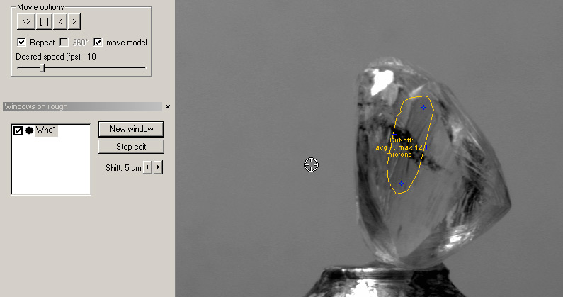
- After finding good position of window plane press «stop edit»
button. You will see color of window in the panel Window rough. Color depends
on depth. Green color of window is optimal depth (average depth less than
10 microns), yellow is permissible depth (10-30 microns), red is inadmissible
depth (more than 30 microns) – cutting of model is blocked.
- Tick on «Model over photo» in the panel «Photo collection»
and check created virtual window.
Play demo 3.3 Mb (Windows
Media Video) 
Download Windows Media Player 10 from microsoft page
|
|